Elisa Alvarado, Sarah Cratem, Ryan Partain, Julia Reidy
Mr. Thomas
AP Physics 2 cmod
13 December 2015
Unit 6: Charged Particles Flow Model Lab Report
Objective: To determine the mathematical and graphical relationship between electrical potential and time for capacitors being charged and discharged when connected to resistors of varying resistivity in series.
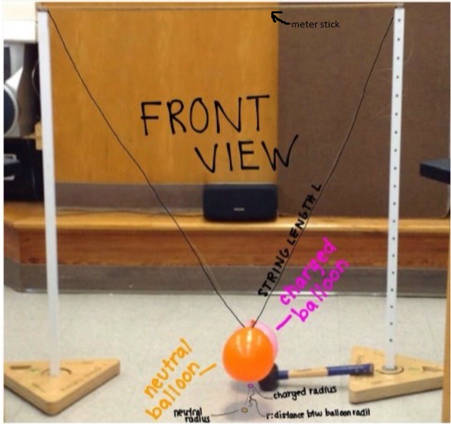
Apparatus:

Procedures:
- Set up the circuit using the 22,000 ohm resistor
- Charge the capacitor
- Discharge the capacitor
- Switch the 22,000 ohm resistor with the 47,000 ohm resistor
- Charge the capacitor
- Discharge the capacitor
- Switch the 47,000 ohm resistor with the 100,000 ohm resistor
- Charge the capacitor
- Discharge the capacitor
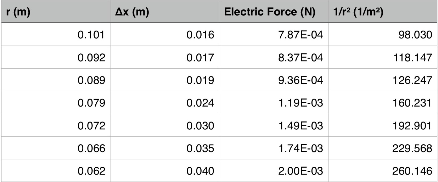
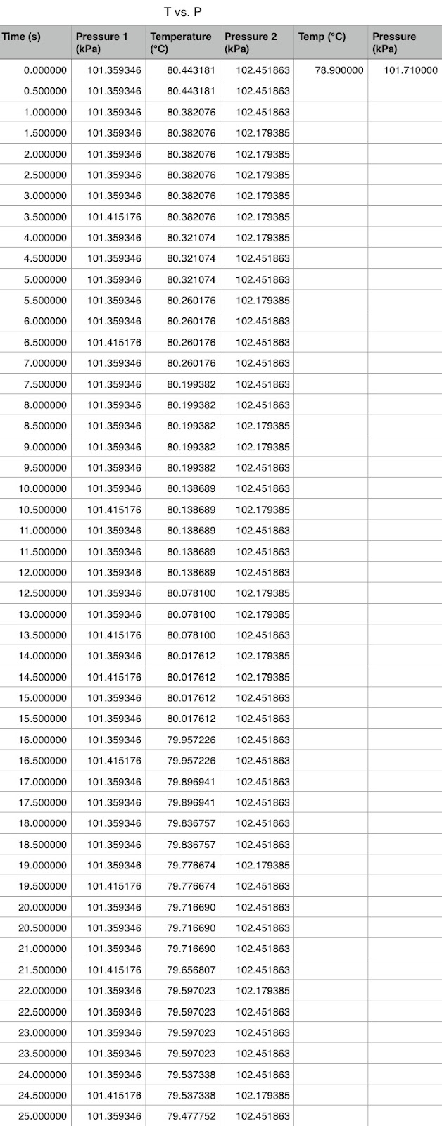
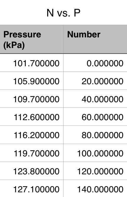
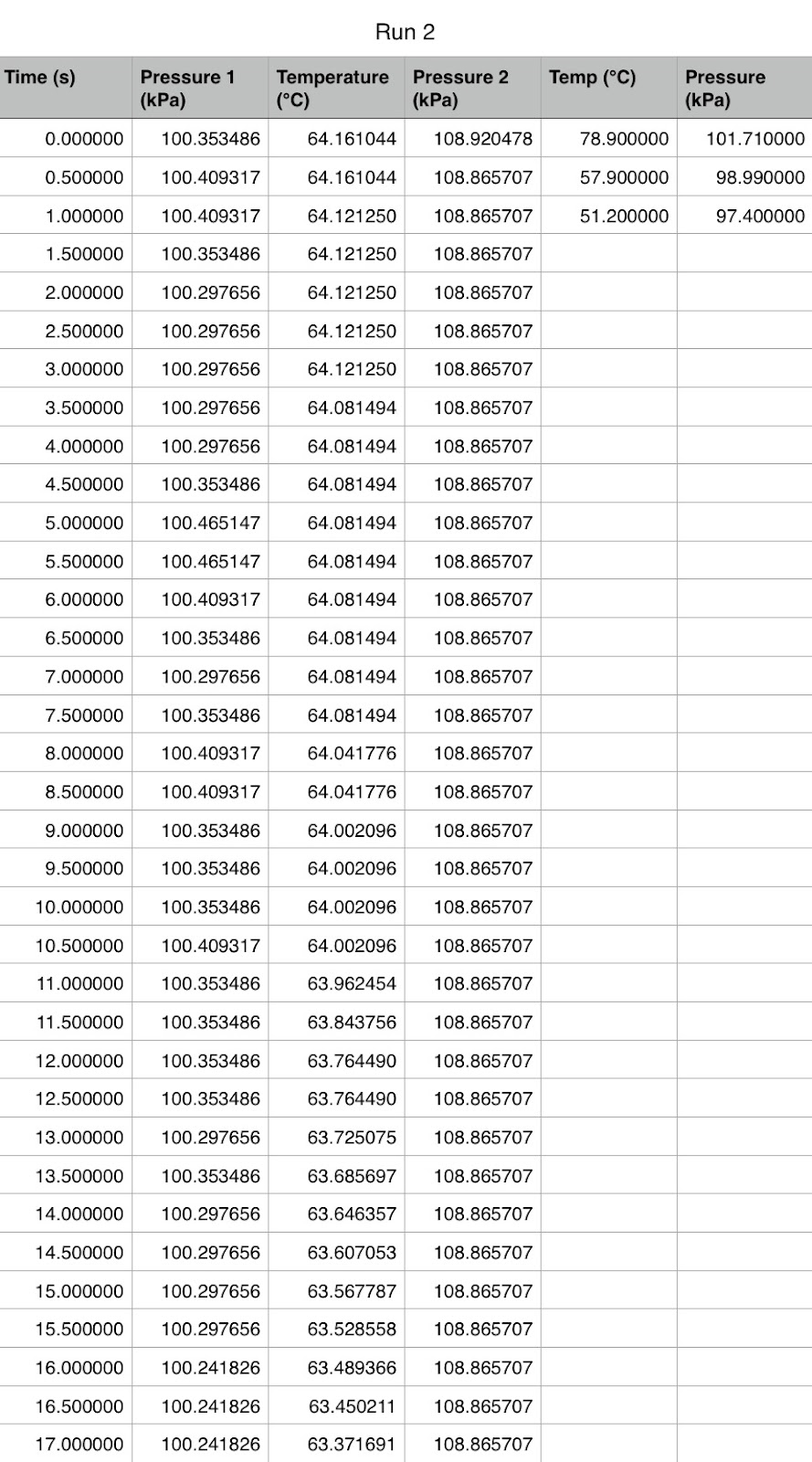
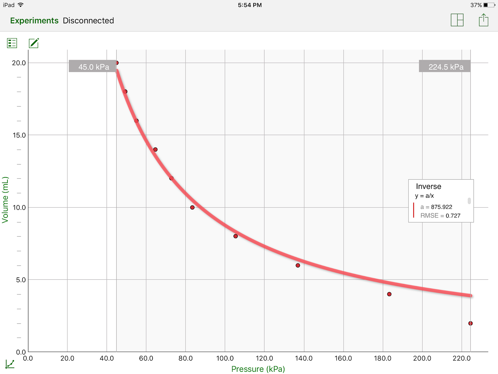
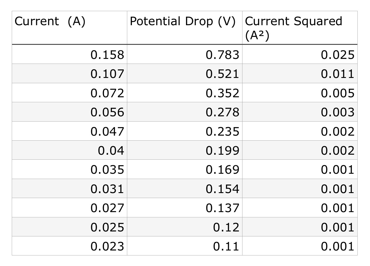
Data Tables: https://drive.google.com/a/bishopkennyhs.org/file/d/0B2kSUAkE0NVYNGRXcENwUDFncVU/view?usp=docslist_api
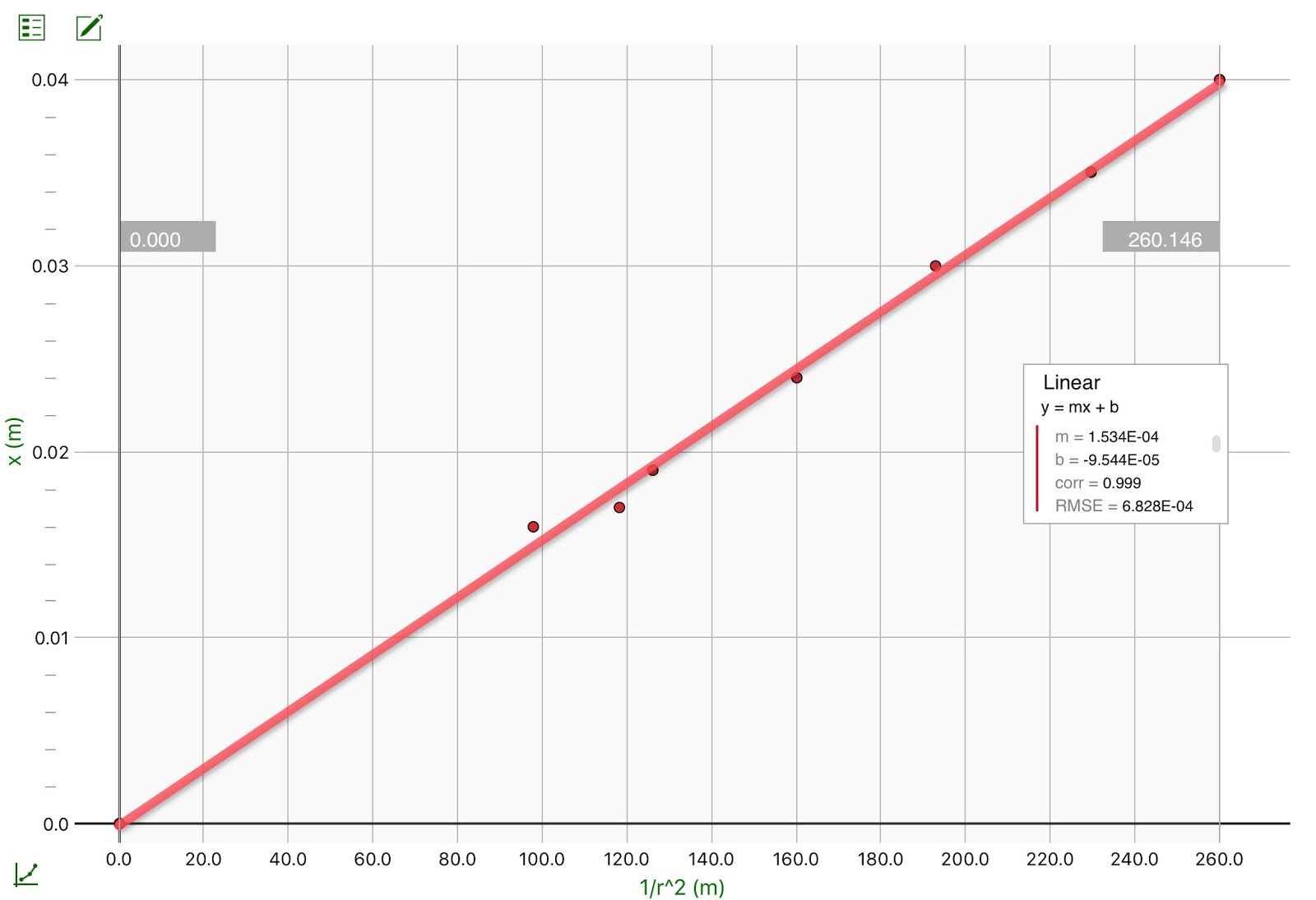
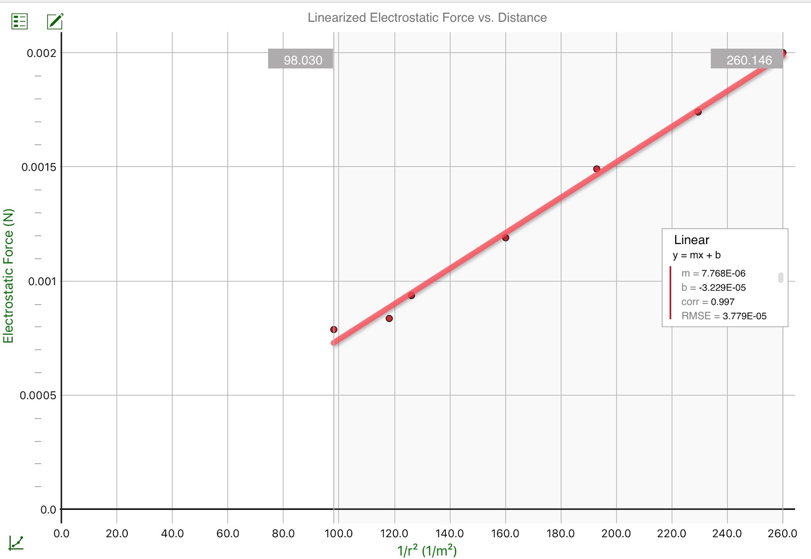
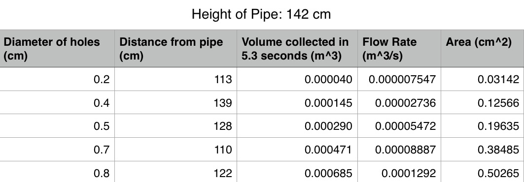
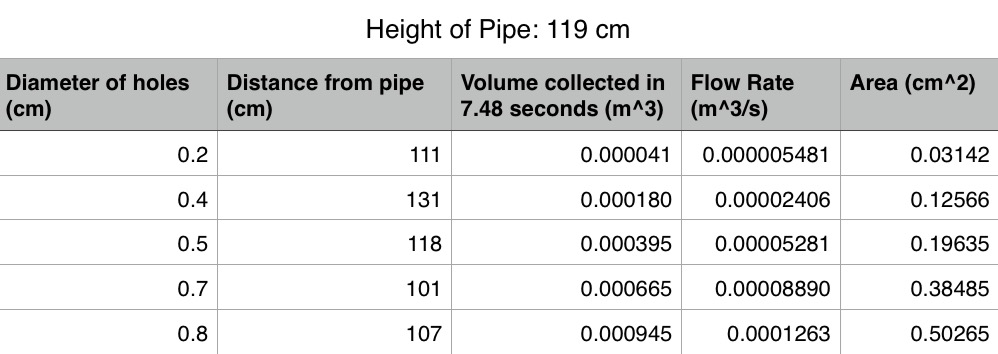
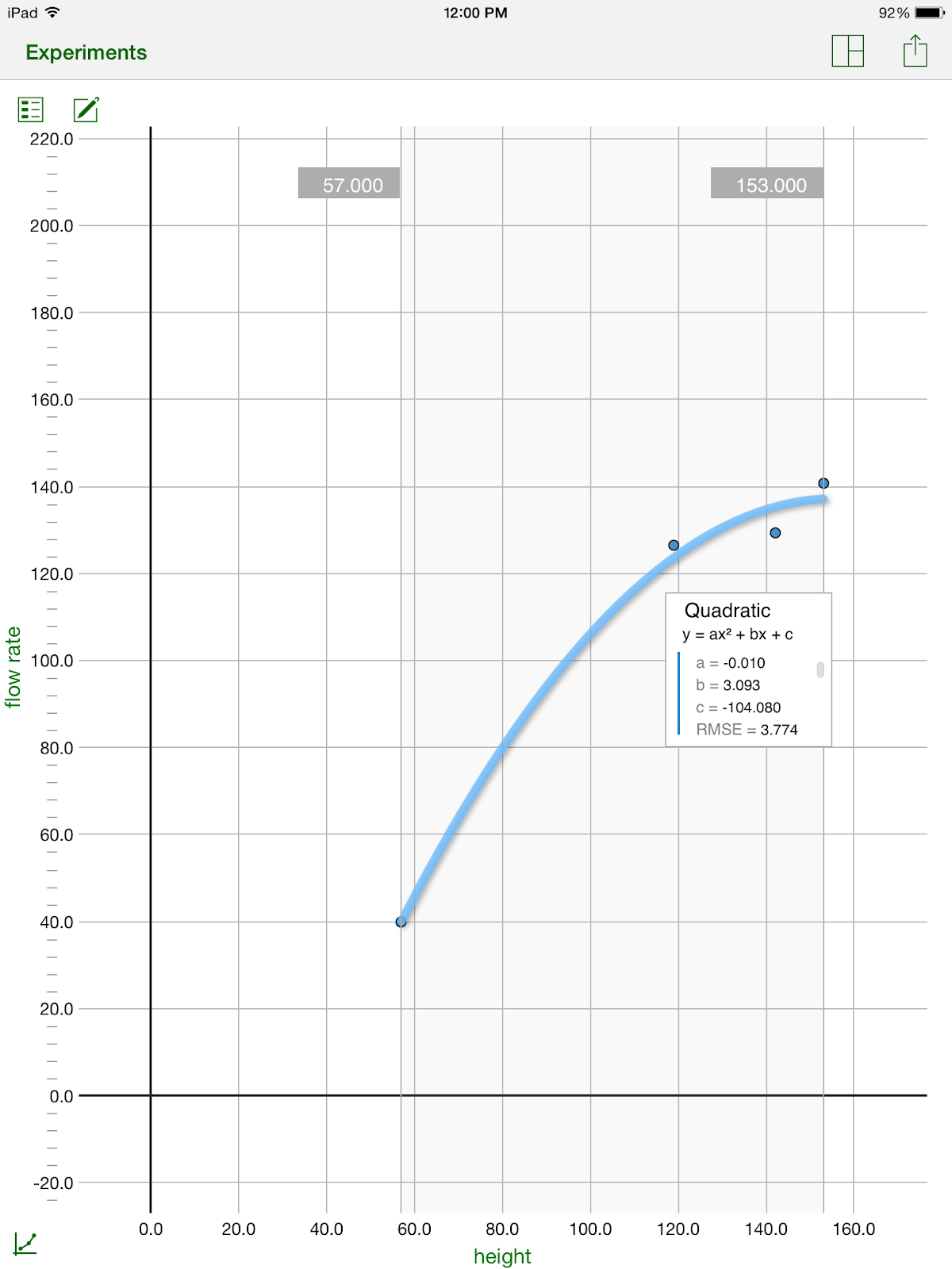
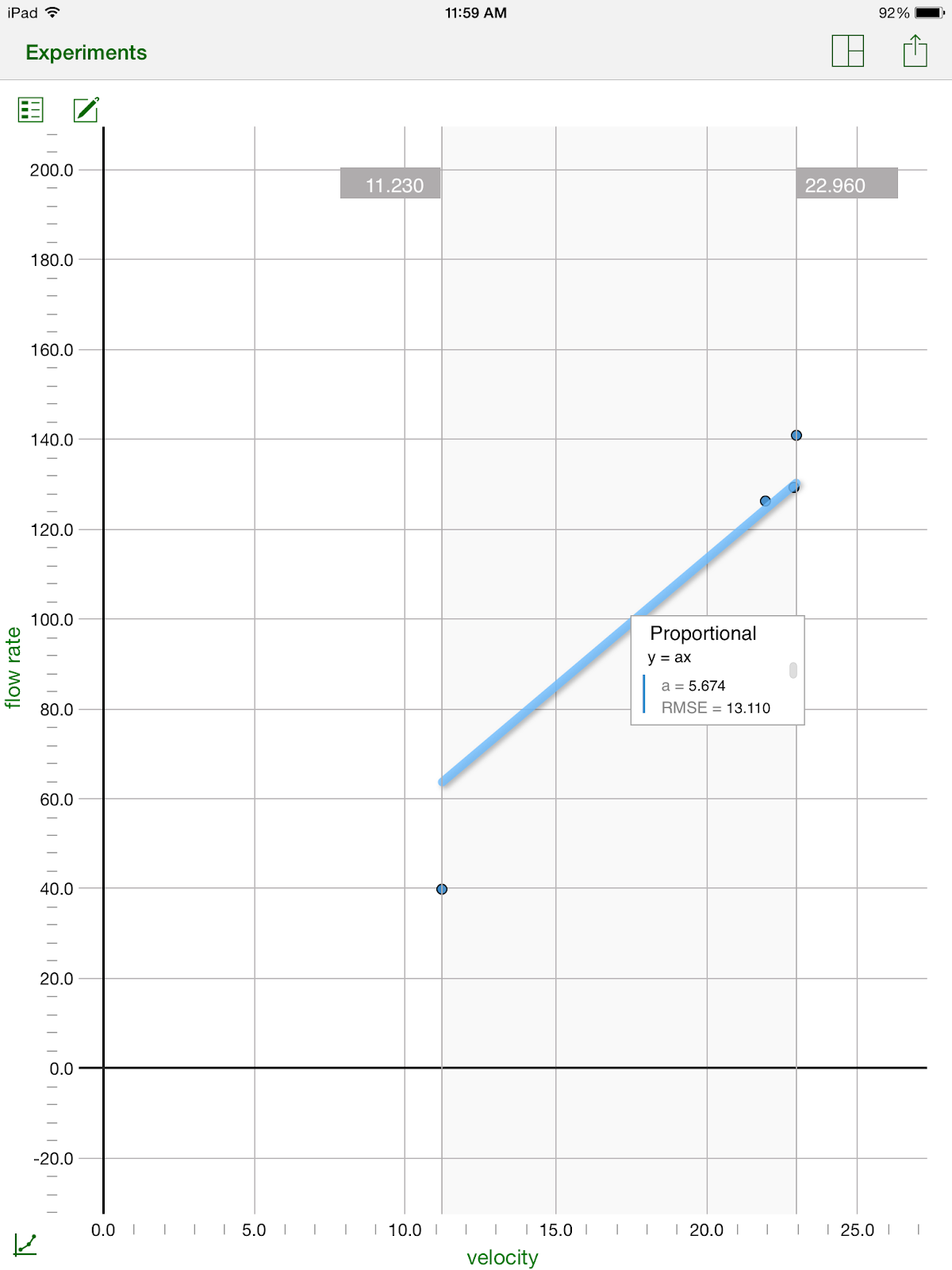
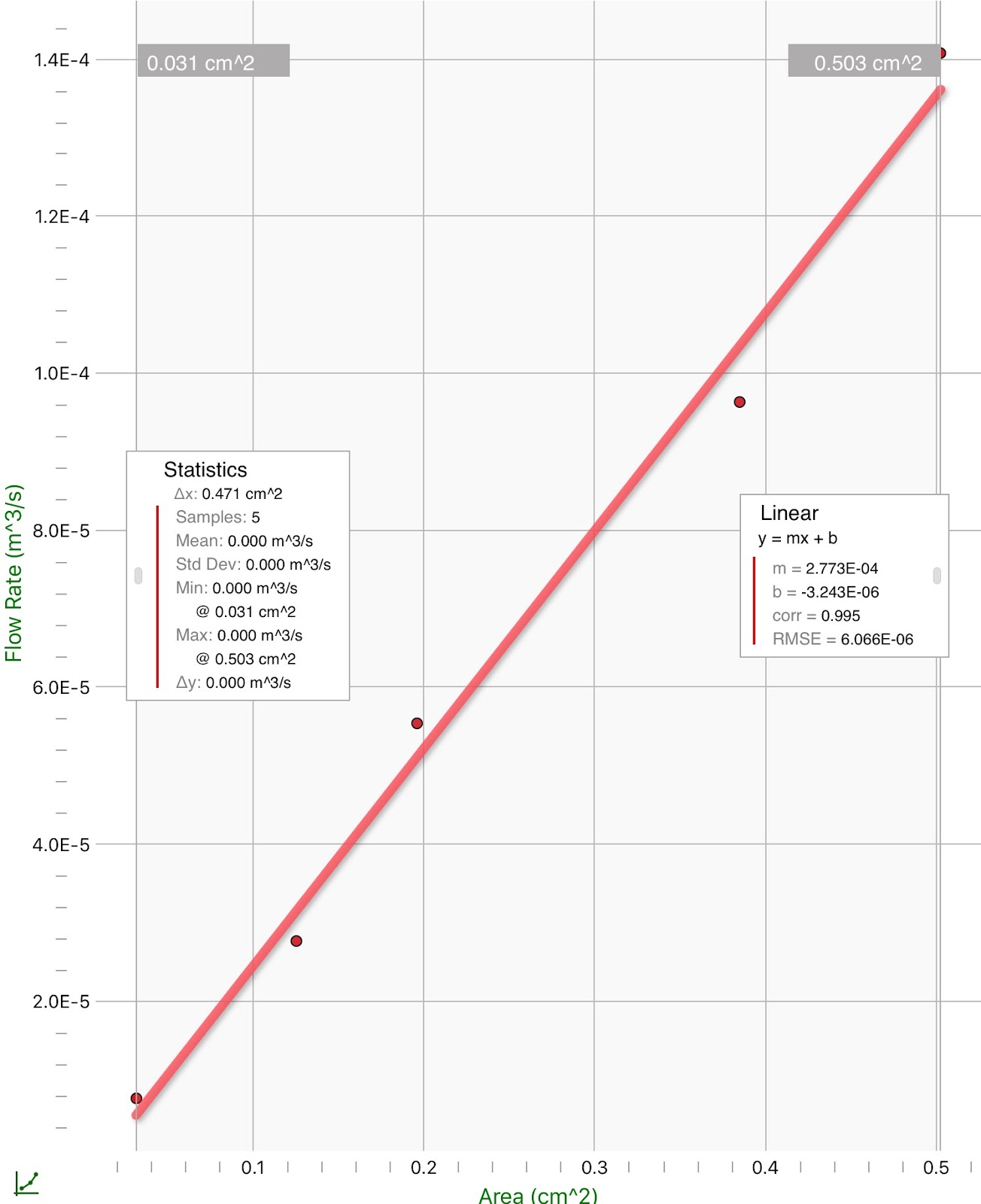
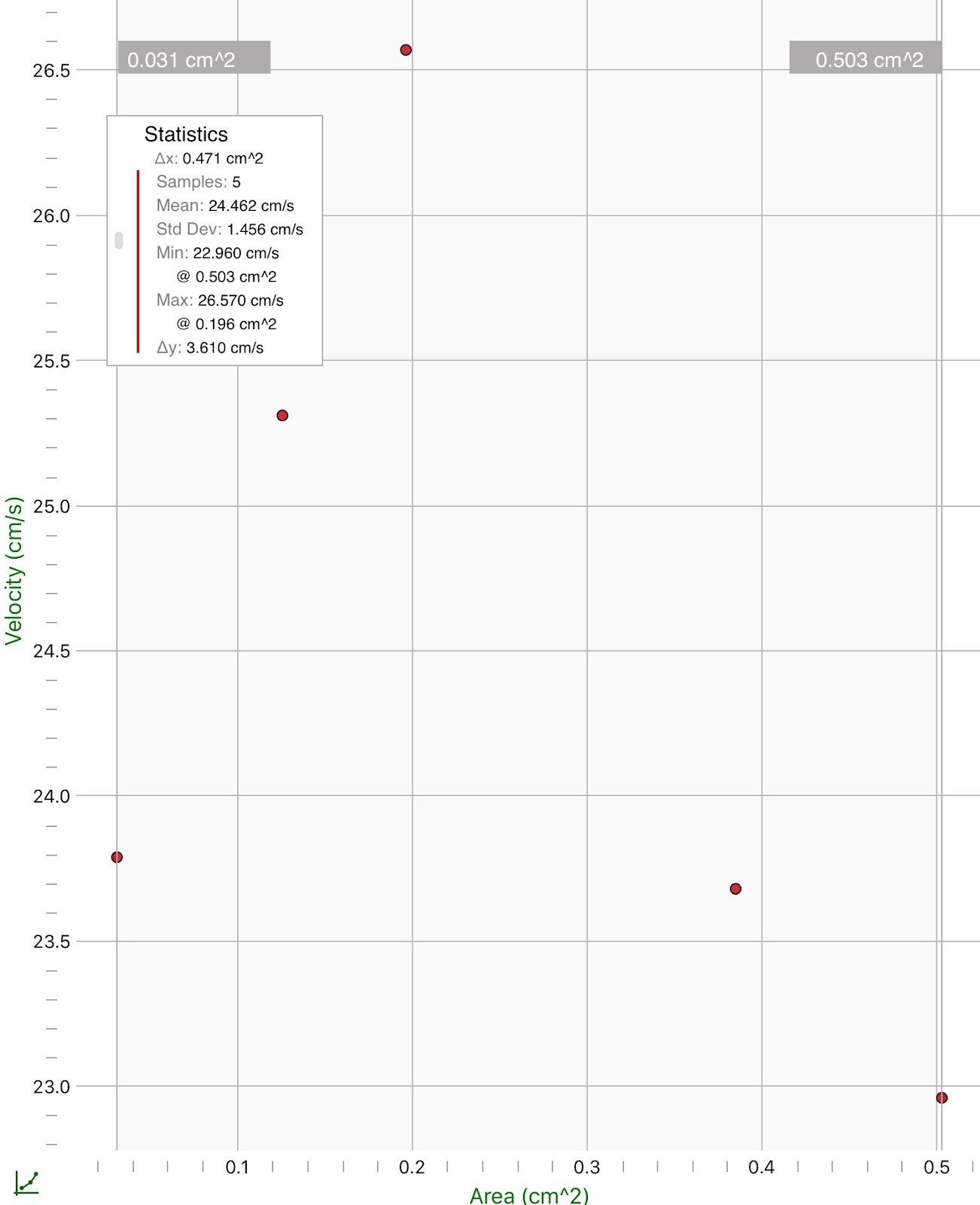
Graphs:
Potential vs. Time
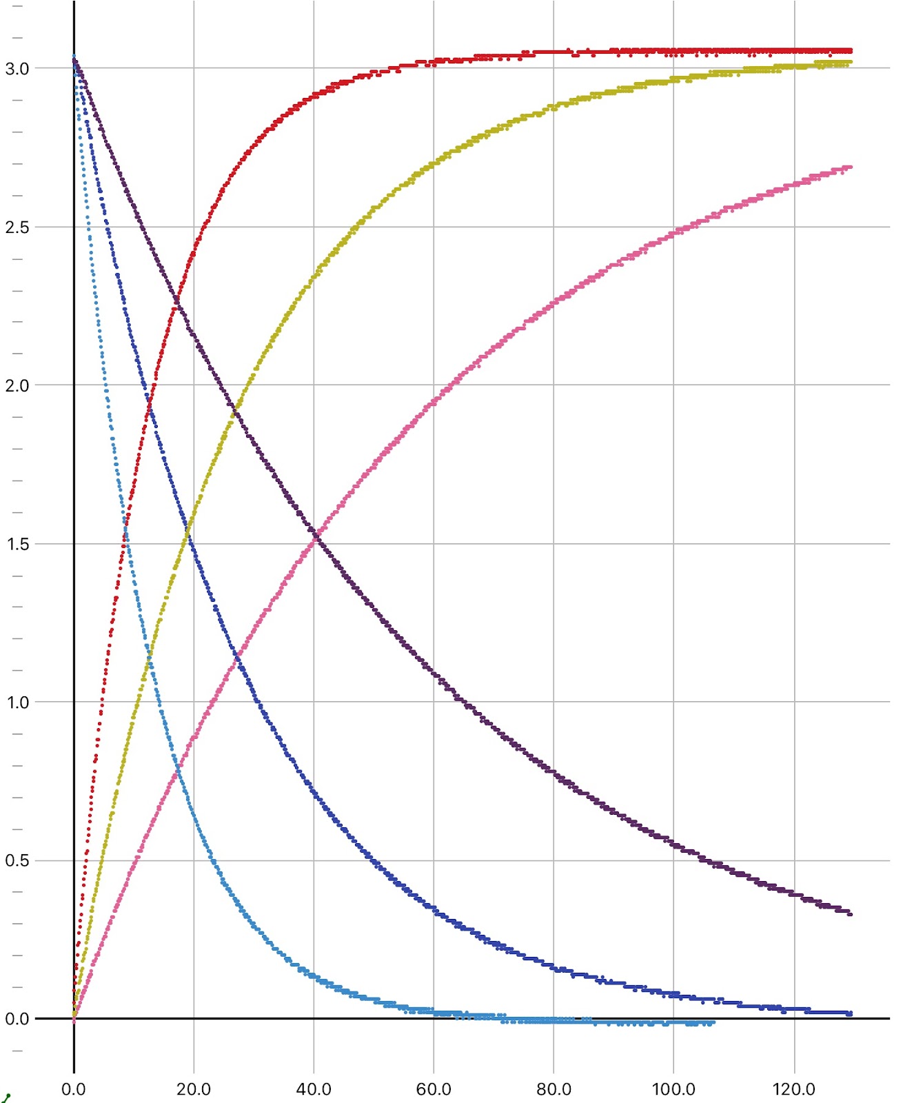
Conclusion: While the capacitors are charging, the potential and time are related by the following equation: Vc=Vsource(1-e^(-t/RC)). The graphical relationship between V and t for charging and discharging is represented by the equation (1-ln(Vc/Vs))=-t/RC. While the capacitors are charging, the potential and time are related by the following equation: Vc=Vsource(1-e^(-t/RC)) which can be converted to ln(1-(Vc/Vs))=-t/RC. We plotted Vc/Vs for the purpose of finding the slope of the final equation and linearizing the graph. The slope was found by the equation slope=1-ln(Vc/Vs)/r where r=resistance with the units of ohms/s. The resistance of the resistor affects the system by lowering the potential and increasing the time it took the circuit to charge. As the capacitance went up the charge and stored charge also rose. Some error could have occurred through a misreading of the devices, batteries not being completely charged, or small amounts of internal resistance on the circuit. The error could be minimized by making sure all equipment is up to date and read properly and carefully.